Computerized Throwie
LED Throwies are an inexpensive way to add color to any ferromagnetic surface in your neighborhood. A Throwie consists of a lithium battery, a 10mm diffused LED and a rare-earth magnet taped together. Throw it up high and in quantity to impress your friends and city officials.
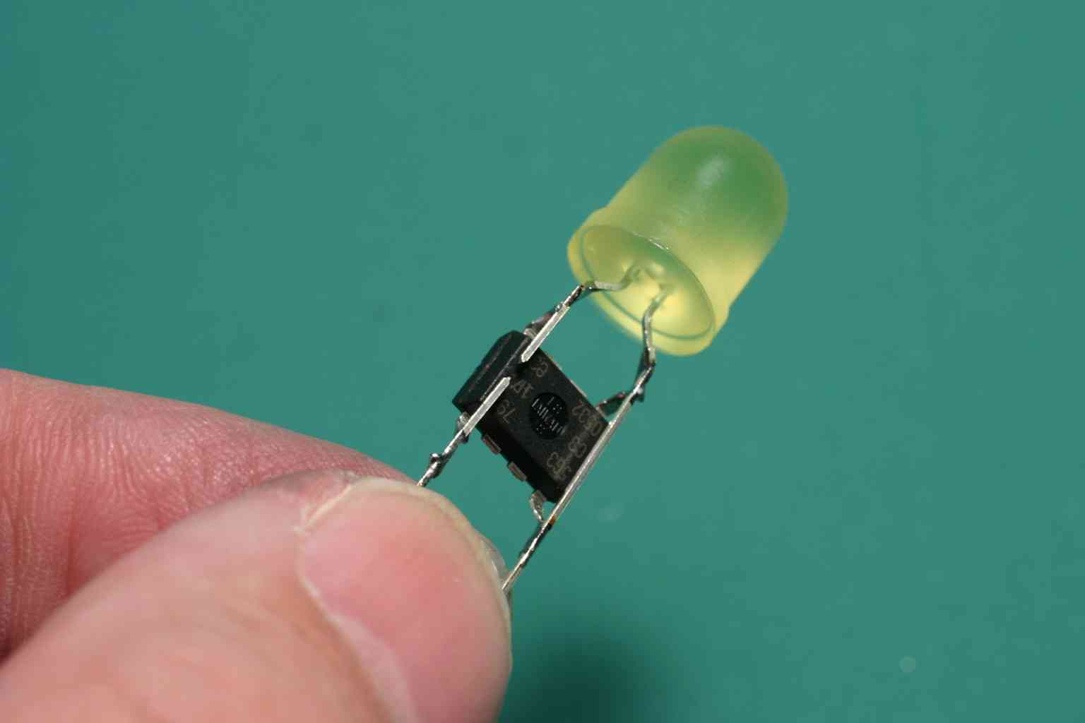
We met the folks from the lab at the MakerFaire; built a few throwies under their direction; and then computerized one using a part loaded with MorseCompanion that we'd been showing off the day before.; ATtiny45 ; --v-- ; +--- rst -|-----|- vcc --->|-+ ; --- | | | ; ----- | | | ; +--- gnd -|-- --|- keyout ---+ ; ----- ; 8MhzMechanically this worked out great. We just clipped off the unused pins; layed the part across the leads of the LED; soldered; and then cut a gap in the ground lead that the computer would electrically "close" to make the Throwie light.
PatCunningham has written an "instructable" for this project and we offer our own version of step-by-step instructions below.
Step-by-Step Instructions
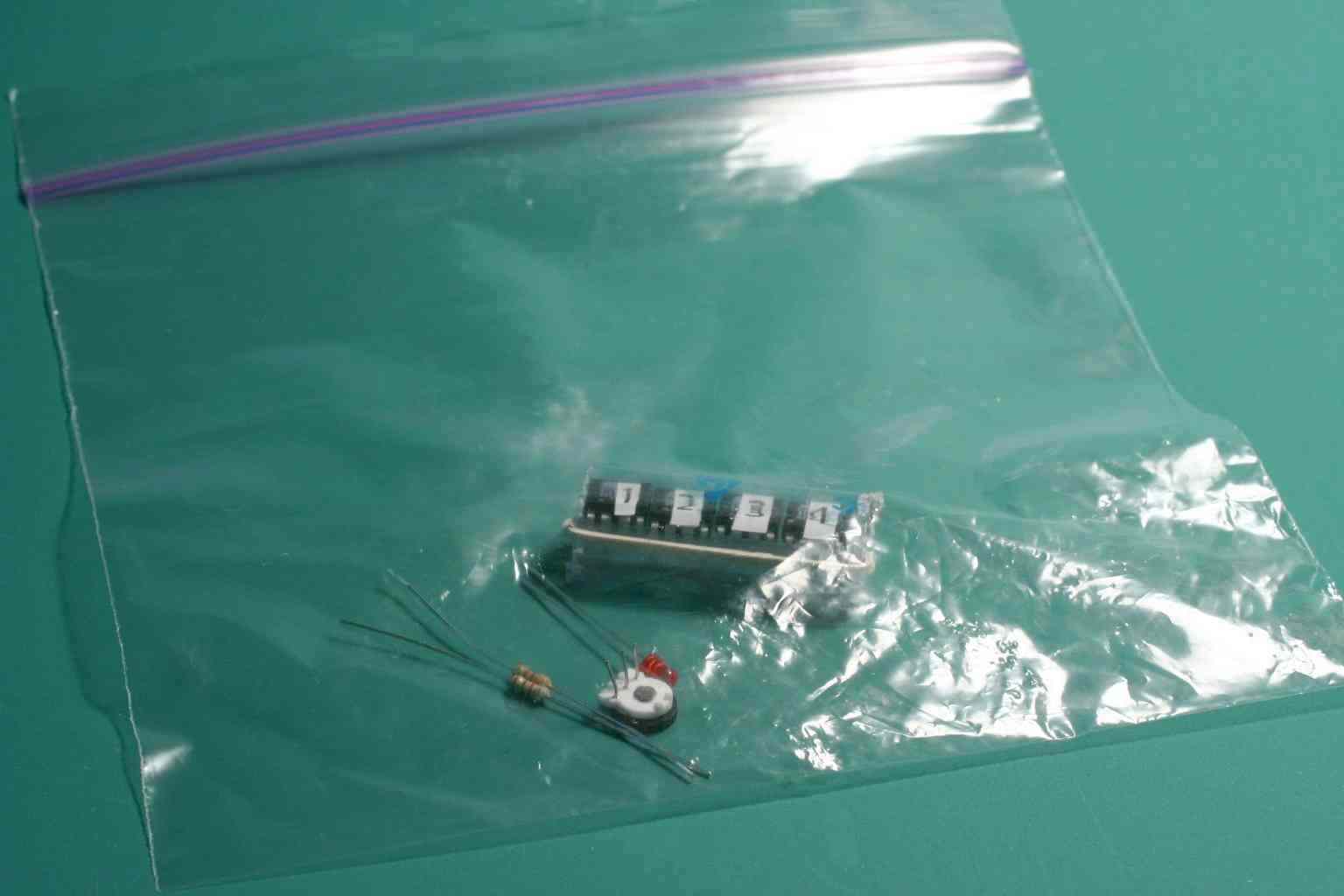
This project is a "mashup" of two projects offered at the MakerFaire. You will need parts from the GRL Throwie kit and the Cybords MakerProject kit.
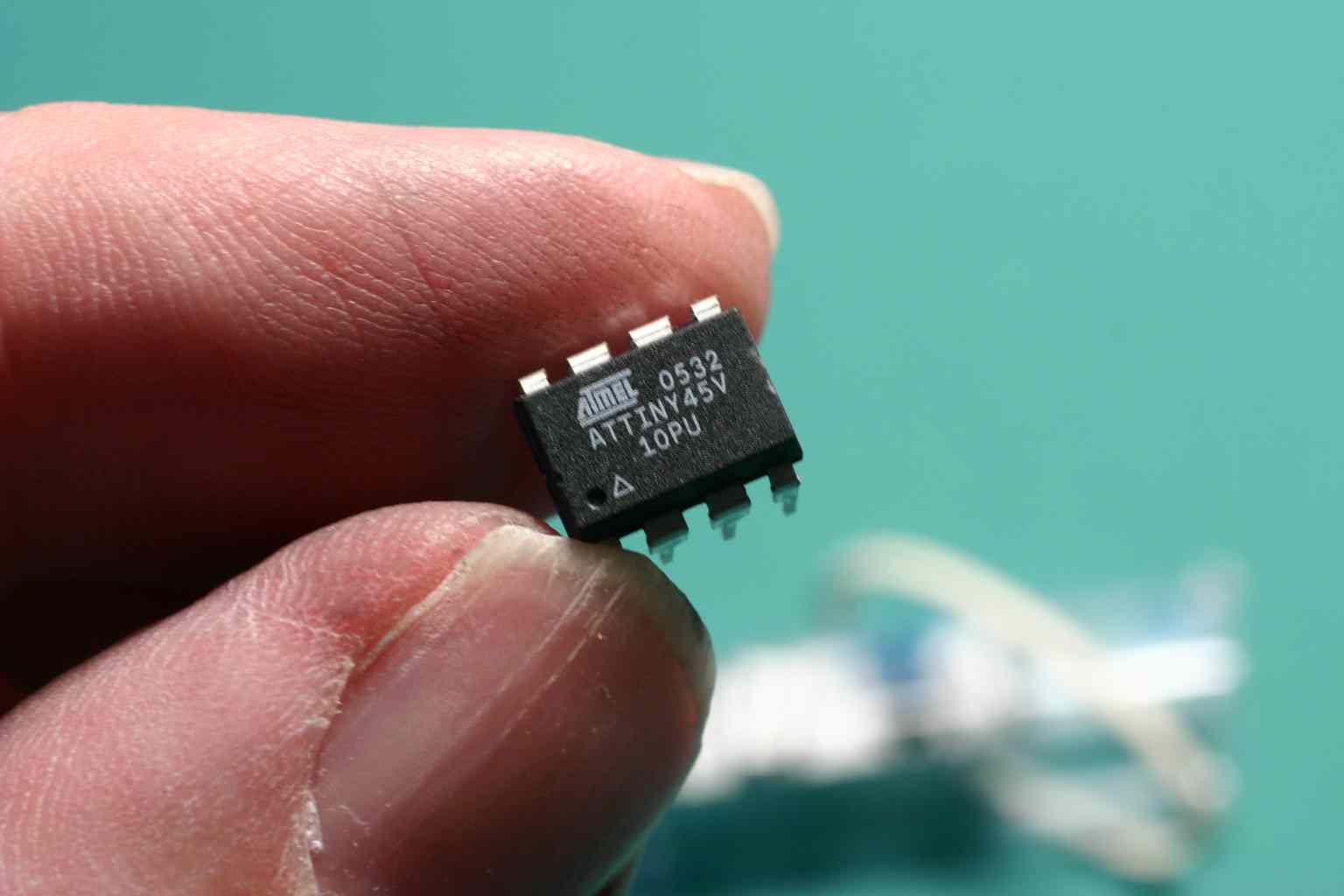
Step 1 Locate the #1 computer from the cyboards kit. This is a Atmel AVR Tiny45 (ATTINY45V) preprogrammed with MorseCompanion. Remove the label which is for identification only.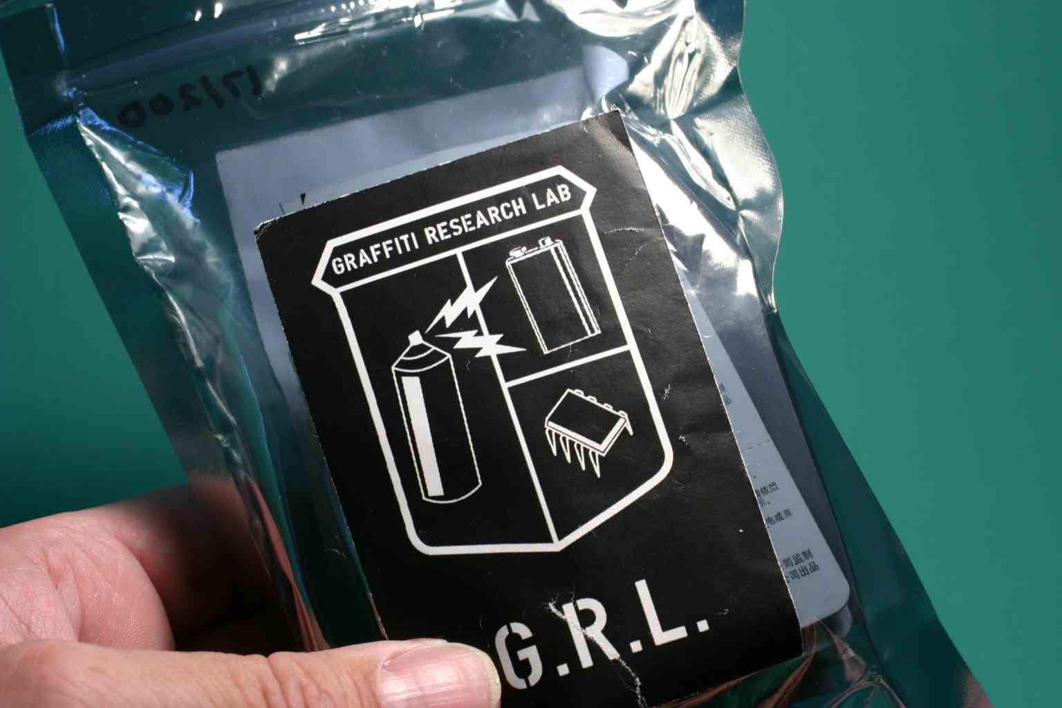
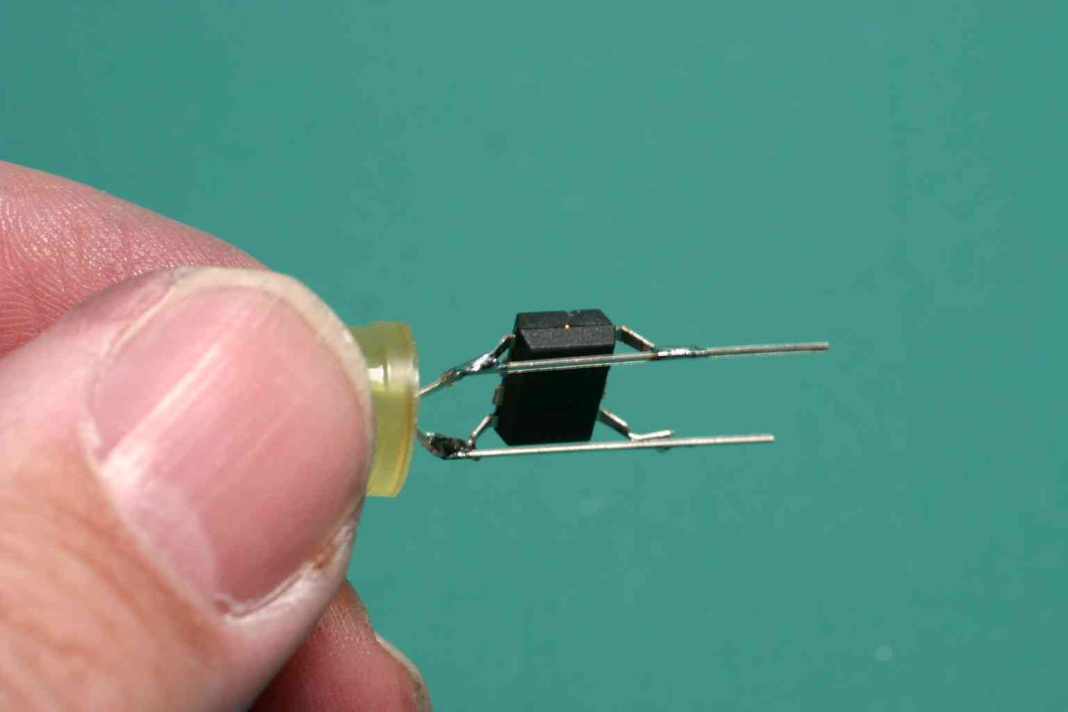
Step 2 Remove unused pins. Bend the center pins back and forth until they break off. Do not remove the pins located in the four corners of the part.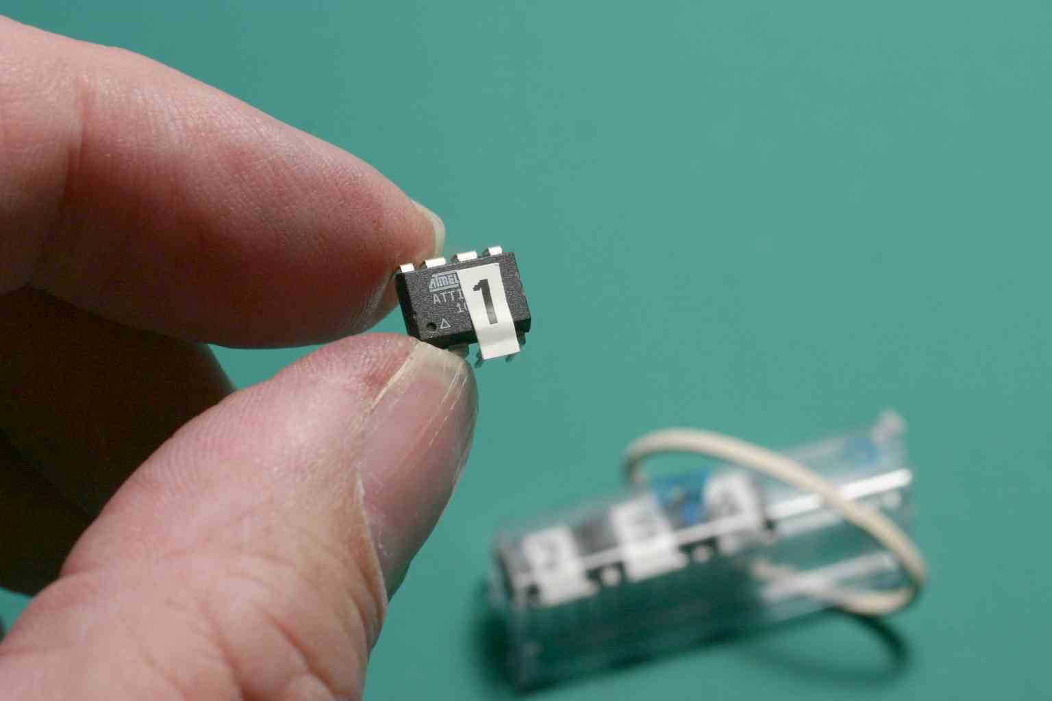
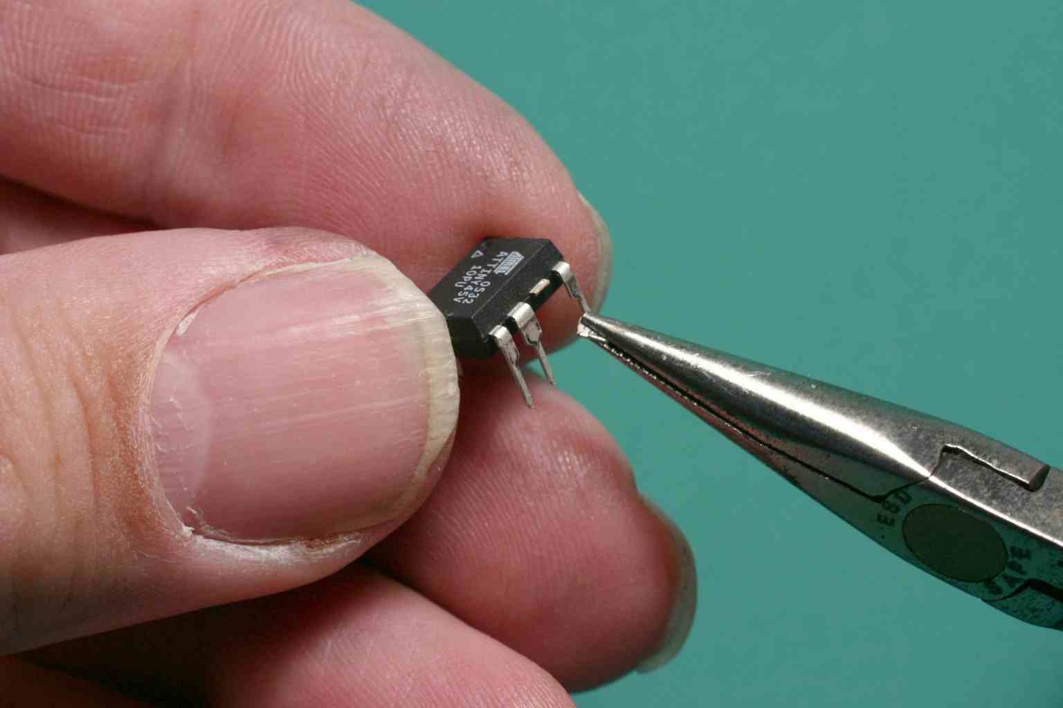
Step 3 Bend remaining pins. Bend each pin 45 degrees away from the center of the part. Then bend the thiner part of each pin an additional 45 degrees until they are horizontal.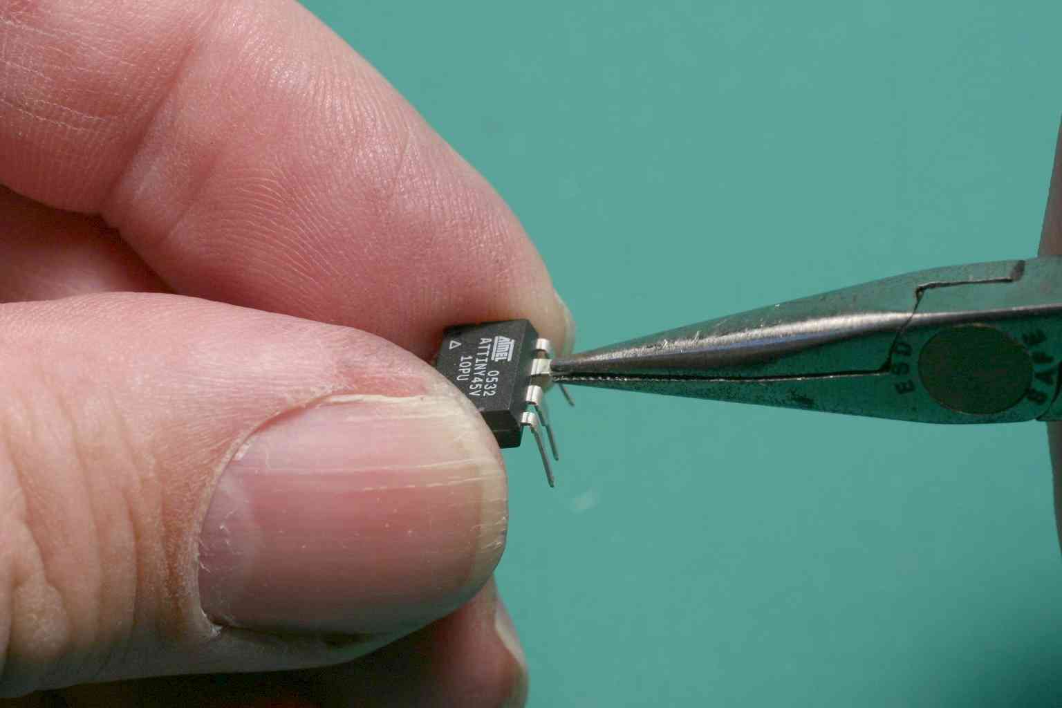
Step 4 Locate a large light-emitting diode (LED) in the GRL kit. Bend both of its pins so that it is has the same spacing as the pins on the computer.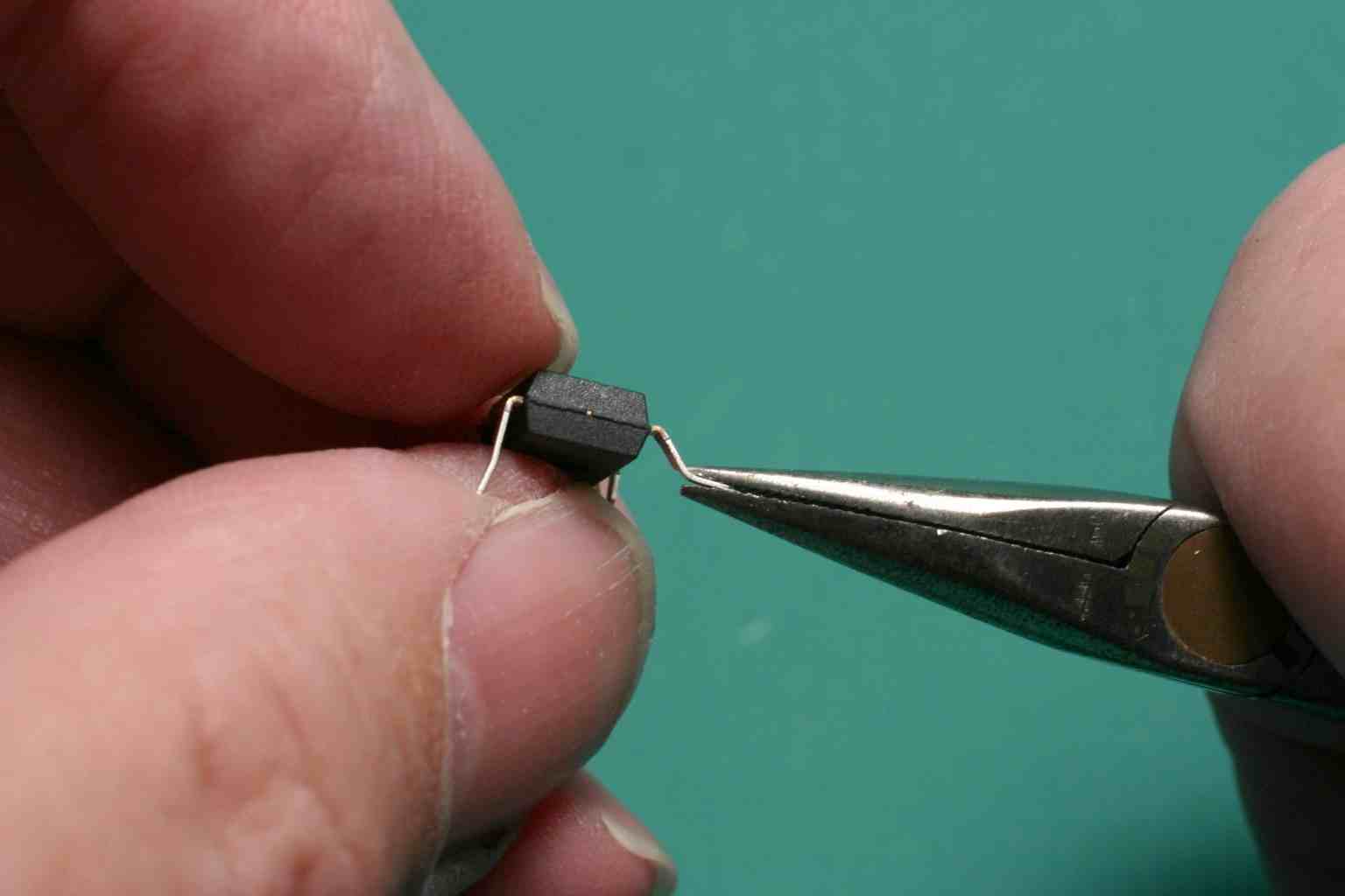
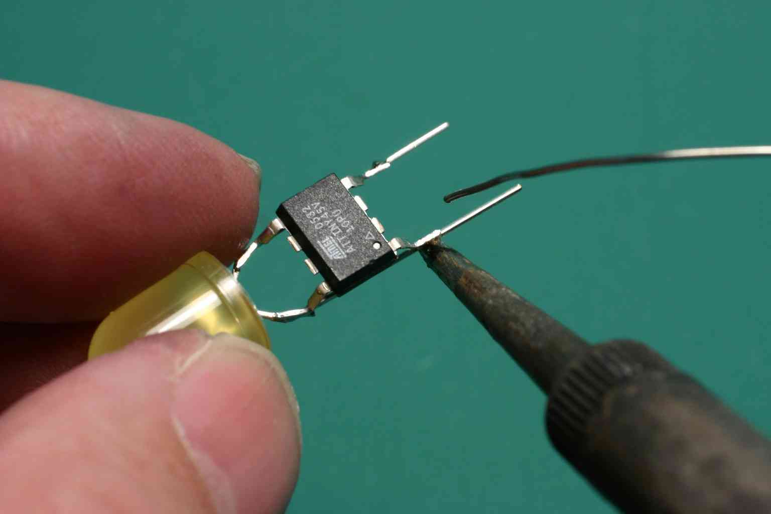
Step 5 Position the computer. Orient the computer so that the top-side (pins 5 and 8) overlay the LED. The pin one marker, a small dot molded into the computer's plastic case, will align with the longer of two leads. Hold the computer in place with needle-nose pliers.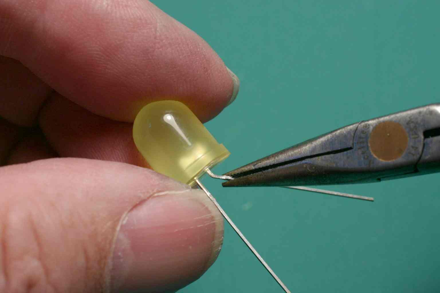
Step 6 Solder the pins. Heat both leads and then apply a small amount of solder. Wait for it to flow. Hold the LED by hand and solder the fourth pin the same way.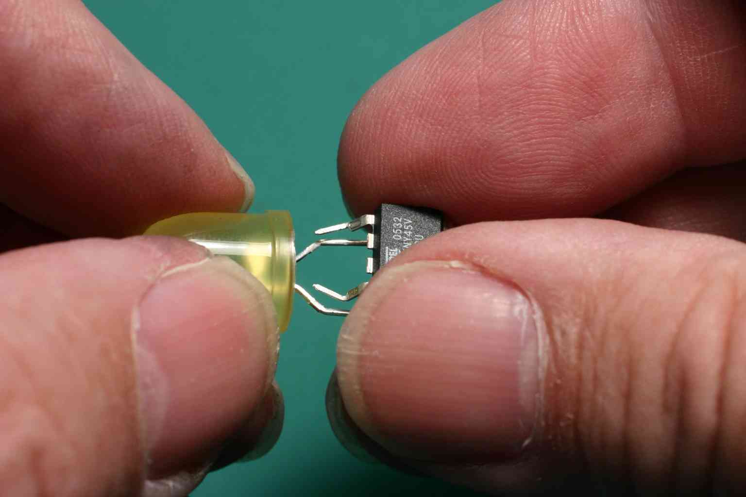
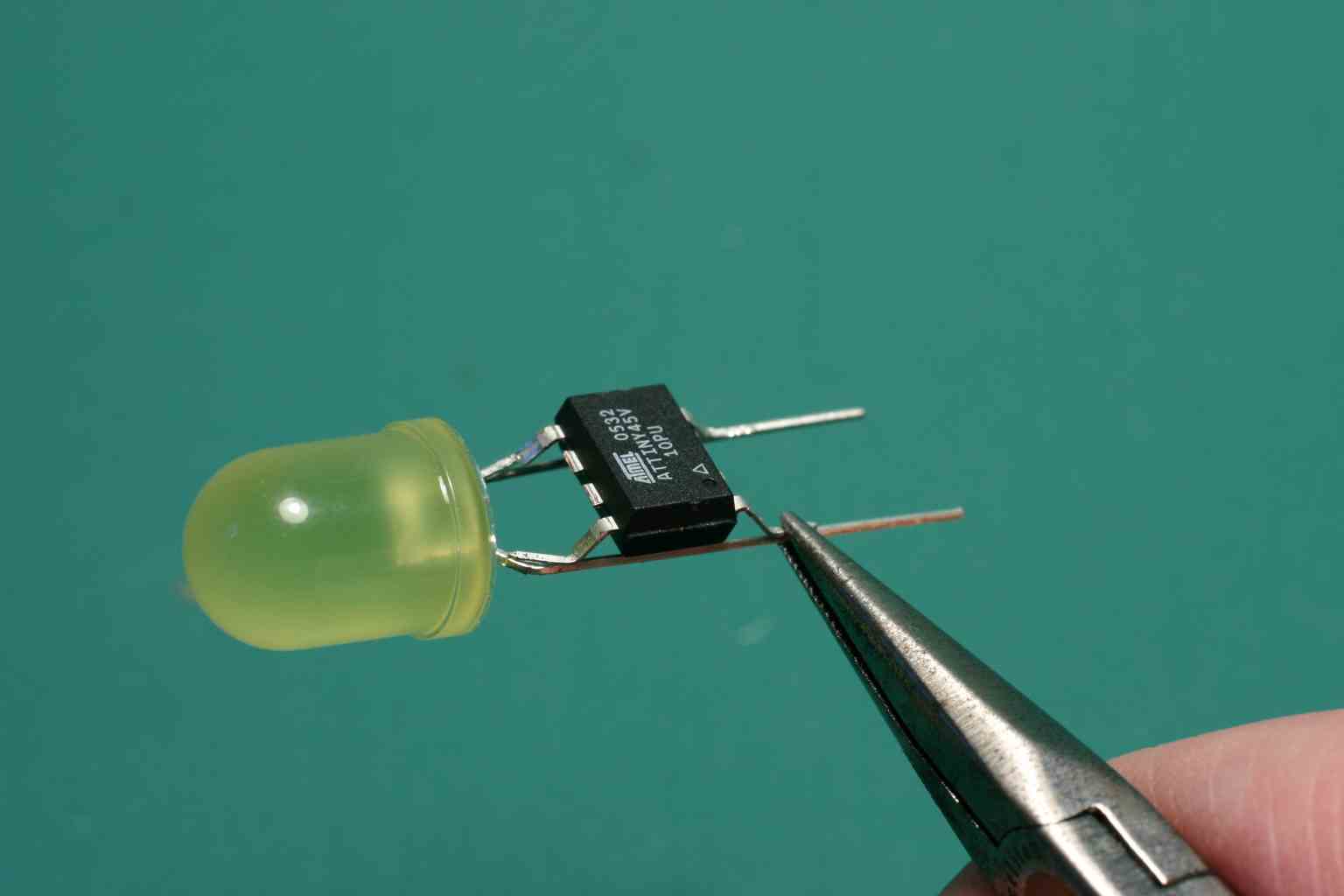
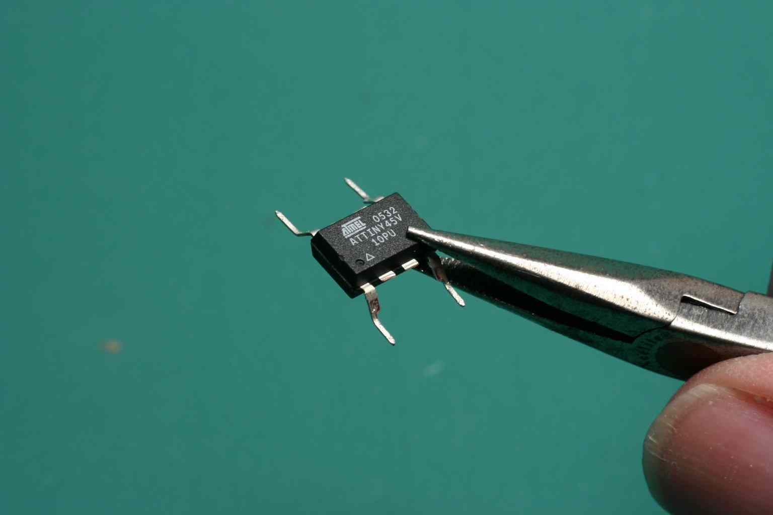
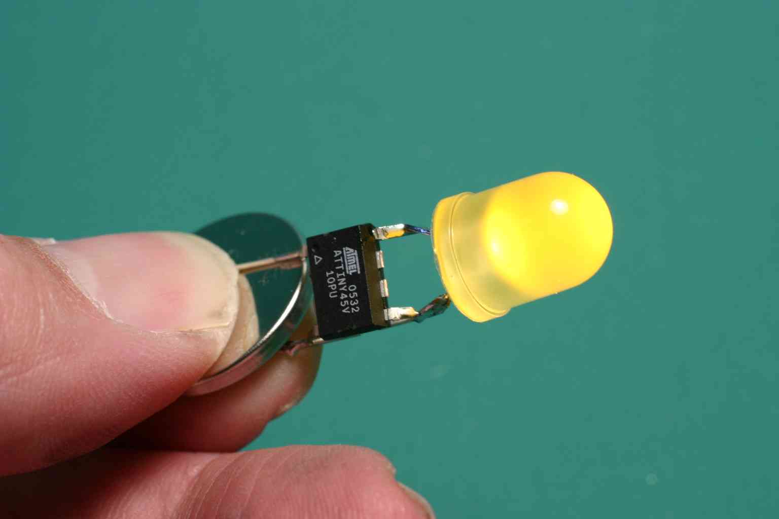
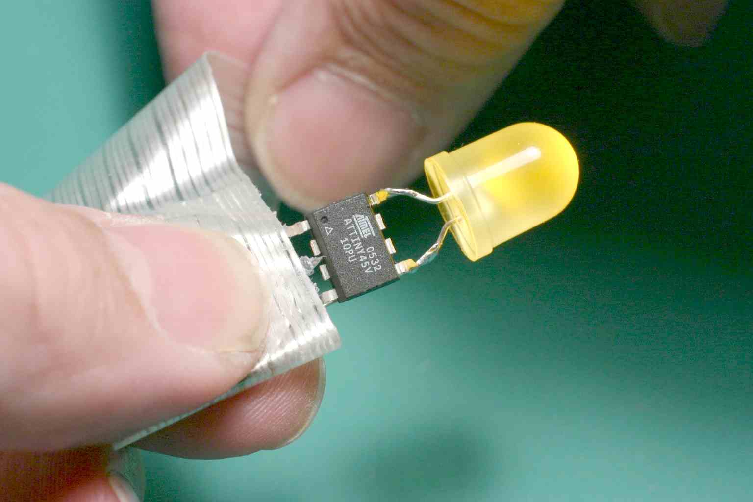
The computer/throwie should look like this.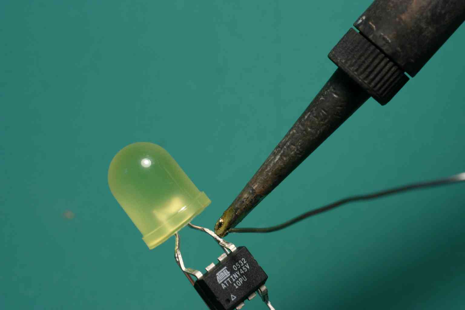
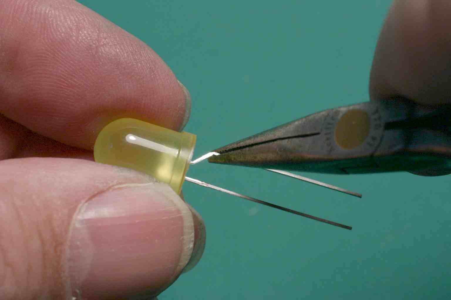
Step 7 Use diagonal cutters to cut the ground (minus) lead between the two pins on the computer. Make a second cut nearby and remove a small amount of metal so that current cannot flow except through the computer.
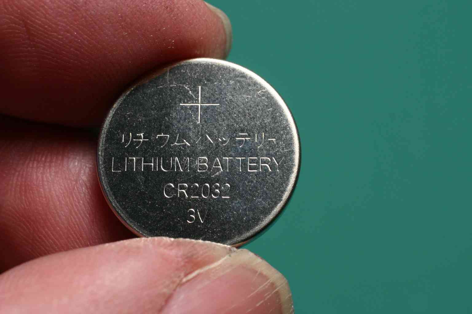
Step 8 Locate the Lithium-Ion battery in the GRL kit. Identify it's plus (+) side.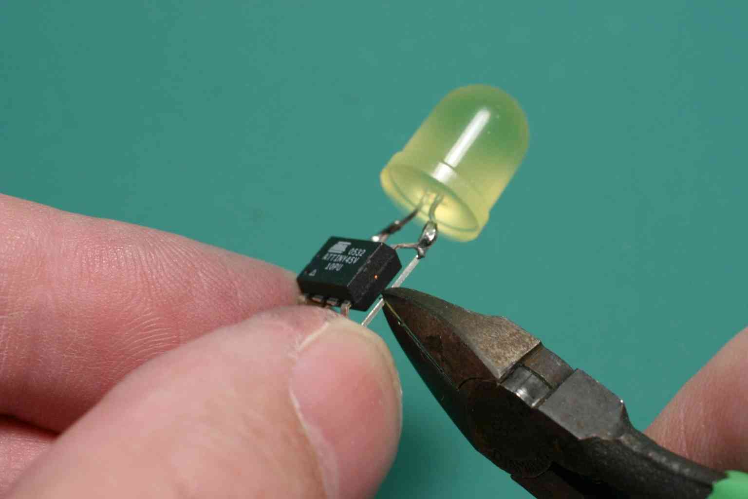
Step 9 Test the part by holding the longer lead against the plus side and the shorter lead against the minus side of the battery. If the light does not light and blink, try reversing the connection or try a fresh battery.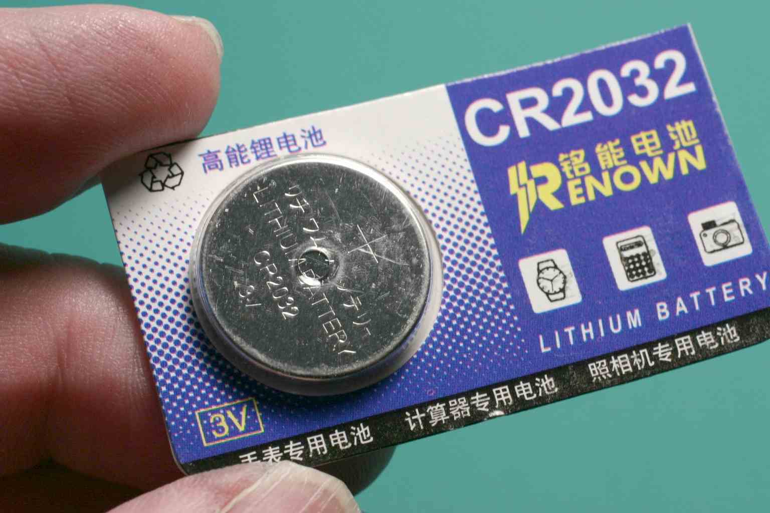
Step 10 Tape the leads. Tape one side, fold, then tape the other. Start at the end of the tape so that there is free tape remaining after taping both sides.
Step 11 Locate a Rare-Earth magnet in the GRL kit. Place it against the first side taped and continue tapeing so that the LED leads and the magnet are held firmly in place.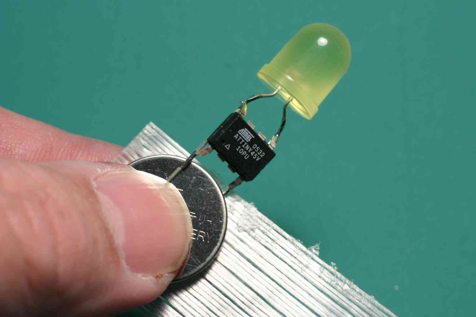
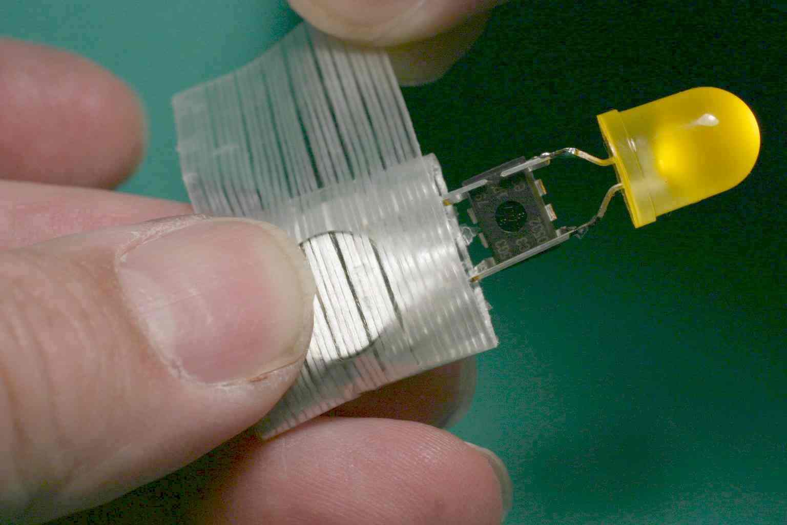
This completes the ComputerizedThrowie. It should be blinking brightly. The magnet is strong enough to lodge the throwie agains ferrous serfaces even when thrown from some distance. Here the thowie is adhearing to the handle of the pliers used to construct it.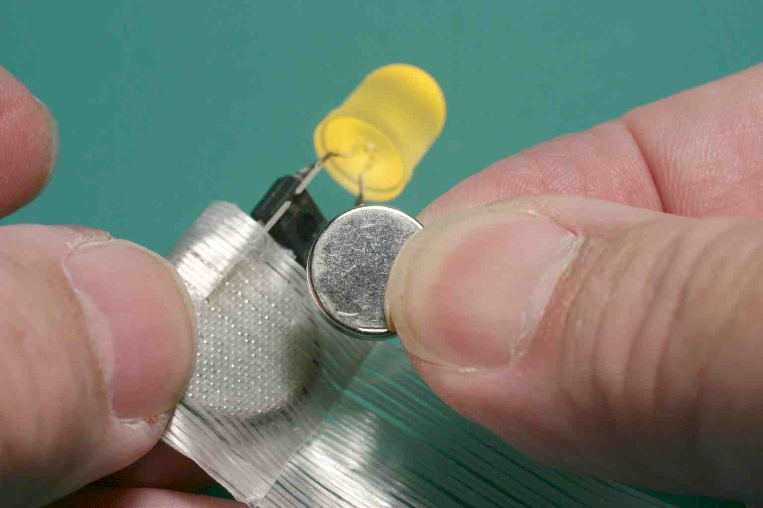
See animated versions of these pictures here: We don't yet know how long the batteries will last. The non-computerized versions last a week or so. The computer takes some additional power but saves some power too by not running the light continuously. The computer will detect low voltage and reset. There may be sufficient battery life left for other applications.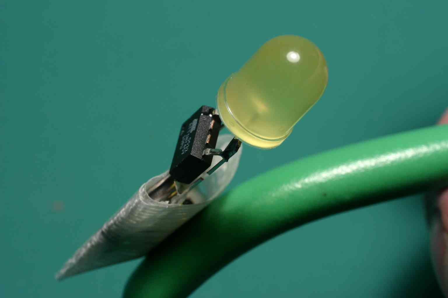

Return to WelcomeVisitors